THE geographic
location of England makes it most vulnerable to attacks from the air, and as a
means of defense the interceptor ‑ fighter planes have been developed. These
venomous single - seaters operate at close range and it is their military duty
to sweep raiding aircraft from the sky. Such planes as the famous Hawker
"Hurricane" and the "Spitfire" are designed to rocket skyward at an astonishing
rate, be fleet enough to overtake the swiftest invader, possess a great degree
of maneuverability and finally be deadly enough to promptly dispose of the
luckless victim.
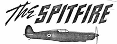
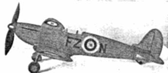
The Vickers
Supermarine "Spitfire" is not a new design; the first of this type being tested
in 1936. Production difficulties plagued volume construction, however, and it
was only recently that complete squadrons of "Spitfires" were in service. Of all
- metal construction, this aerial terror is not only one of the world's best
performers but it is also one of the most attractive. A liquid cooled Rolls
Royce engine of 1030 horsepower pulls it along at a maximum speed of 367 miles
per hour - its diving velocity exceeds even that of the famous Curtiss 75‑A for
it is said that a "Spitfire" attained a speed of nearly 700 miles per hour in a
similar plunge. Eight Browning machine guns jut from the wing's leading edge
making it one of the heaviest armed single - seaters. Squadrons of these fiery
fighters are constantly in readiness to intercept Nazi trespassers.
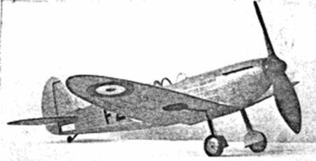
The model retains
the attractive appearance and streamlines of the original and an effort has been
made to simplify the manner of construction as much as possible while still
retaining the desired features.
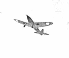
The satisfaction
it is sure to afford, whether on display or in flight, will more than compensate
for the time and effort expended on its construction. After becoming familiar
with the plans and the procedure of construction, you may start to build the
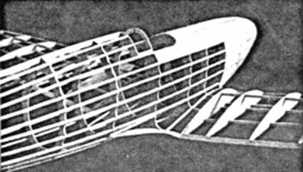
Fuselage
The fuselage is constructed about a top and
bottom keel. To obtain the shape of the keel pieces it will be necessary to
trace the top and bottom outlines of the side view. A depth of 3/16" will be
about right and the keels should be cut from 1/16" sheet balsa. The bulkheads
are cut from 1/16" sheet also; two of each type are needed. Cut only the notches
shown; the purpose of this is to aid in properly aligning the stringers. Enough
of the bulkheads have notches cut in them to insure proper spacing of the
stringers and it will be a simple matter to cut the remaining ones as needed.
Pin the keel pieces into position over the side view and cement half of the
bulkheads to place. Remove from the plan and add the remaining formers. Next the
1/16" square middle stringers are added to each side. Exercise caution to avoid
pulling the fuselage out of line. Once a stringer is secured to one side of the
structure always attach one to the corresponding position of the other side.
Check continually to assure a properly aligned structure.
The nose of the
original model was "filled-in" with 1/16" soft sheet balsa. This is not a
difficult job but it does require time and patience. Cut individual pieces of
balsa so they will fit snugly into each open space between the stringers and
bulkheads. When dry the whole nose is thoroughly sandpapered to a smooth,
pleasing shape. Cut the nose block from a 1/2" thick block and cement it to
place. It is advisable to lightly cement the 1/8" nose plug fast, too, so the
entire nose can be shaped attractively.
Cement a "w-I"
rib to each side of the wing root, being careful to make the angle of incidence
identical to that of the plans. The trailing edge of the wing root, cut from
1/16 sheet, is trimmed to the correct size and glued to place. Brace the root
bulkheads with pieces of 1/16" x 1/8" hard balsa as indicated by the dotted
lines on the bulkhead patterns. 3/32" square pieces are fitted between the root
rib and the fuselage to form the leading edge. A 1/8" thick false rib is fitted
against the fuselage by the "cut and try" method - it extends from the leading
edge to bulkhead number b-3. Several lengths of thin bamboo may be attached to
the bulkheads to help round out the wing root.
Prepare the
fuselage for covering by thoroughly sanding the whole structure. For the best
covering job only those members of the fuselage which run from nose to tail
should touch the paper, so use a piece of sandpaper wrapped about a pencil or
similar round object to scallop the bulkheads.
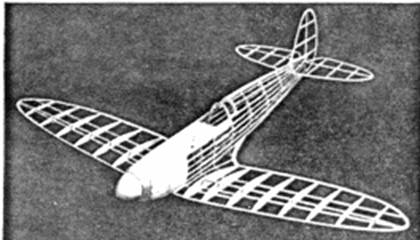
Wing
Since the wing is
elliptical in plan form, all of the ribs in each half are different. Select a
sheet of soft grade balsa for all of the ribs except "w-l" and "w-2" which
require a stronger variety. Cut the required number of ribs and sandpaper them
smooth. Notches must be cut with accuracy to insure a neat job when completed.
The wing's trailing edge is cut from 3/32" sheet; the tips likewise. Select hard
3/32" square spars since they must resist the shock of landings. Assemble the
parts directly over the plans and cement the joints firmly. When dry, the halves
are removed from their jigs, trimmed and sandpapered to their final shape.
Tail Surfaces
The Spitfire's
tail surfaces haven't sufficient area to insure stable model flights so we have
enlarged them to more suitable proportions. Build the stabilizer in one piece
for greater strength. Outlines of the stabilizer and rudder are cut from 1/16"
sheet; ribs are 1/16" square. Additional strips are cemented to both sides of
the ribs and when dry they are cut to a streamline shape.
Propeller
In all
probability your Spitfire will need some extra
weight in the nose to help balance
the long tail moment arm, so we advise the use of a white pine propeller. A
hardwood prop, while a bit more difficult to carve, will take more abuse. Lay
out the blank, as indicated, on a block 9" x 1 1/2' x 1". Cut the blank to shape
with a jig saw, etc. and then carve a right hand propeller. Finish the back face
of the blades first and then reduce the front face to the proper thickness.
Shape the blades so they resemble the wood props used on early Spitfires.
(Latest models of this fighter are equipped with three blade constant speed
metal propellers.) The huge spinner will easily hide a freewheel device which
should be used to improve the model's glide. Make the spinner from hard balsa
and fit it neatly to the prop hub. The application of several coats of clear
dope with light sanding between each will prepare the prop for a smooth finish.
Remove the nose
plug and cement a block 1/4" x 5/8" x 5/8" to the back so it will fit neatly
into the hole in the nose. Drill a hole through the plug and cement washers to
both sides so the prop shaft will revolve smoothly. Bend the propeller shaft
from .040 wire; several washers will be needed between the prop and nose plug.
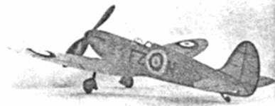
Covering
Cover the whole model with
colored tissue to help keep the weight at a minimum. The model pictured is all
red but the planes at war are camouflaged with dull green and brown paint. Cover
the fuselage first, using banana oil to fasten the tissue. Numerous small pieces
must be used to prevent wrinkles. Trim the surplus paper with a sharp razor
blade and then carefully overlap the next piece. It is not necessary to attach
the paper to all of frame just apply adhesive to the outsides of the area
being covered. Cover the top of the wing with several pieces, if necessary, to
avoid wrinkles. The undersurface of the wing is covered from the third rib to
the tip, only, since the landing gear must be attached to the spars once the
model is assembled. Spray a fine mist of water on the covered parts to tighten
the tissue; pin the wings and tail surfaces to a flat surface to keep them from
warping. Do not dope the covering until the parts are assembled.
Block the
fuselage into a level position so the model can be assembled accurately. Attach
the wings first; do not spare the cement for the wings are subject to the force
of landings. Check to ascertain that the incidence of each wing panel is the
same. The tips should be raised 2-1/8" for the correct dihedral. To attach the
stabilizer it will be necessary to cut the tailpost and bulkhead number 10 in
order that they can be sprung apart far enough to admit the stab. Cement the
rudder on and check for correct alignment. The landing gear struts should be
bent to shape and attached; the plan shows how the .040 music wire is formed so
as to join the spars and second rib of each wing. Draw a front and side layout
to aid in bending the wire accurately and be sure to make a right and left
strut. Use strong silk thread and neatly bind the struts to the spars. Once the
alignment is satisfactory, apply several coats of cement over all the buildings
as well as the adjacent spars and ribs. The remaining uncovered parts should now
be covered.
Complete the
construction by adding the various details. The cockpit enclosure is thin
celluloid; paper patterns should be shaped correctly before the celluloid pieces
are cut. Rubber tubing of the correct size makes excellent covers for the
landing struts, but if it is not available, bond paper should be wrapped into
tubes of the correct size. One or two coats of clear dope are brushed on the
covering; do this in a dry room to avoid "blushing." Check continually to
prevent warping of the flying surfaces. Thin strips of black tissue should be
doped to the covering to represent the control surfaces. The insignia used on
the original model was made from colored tissue, too. Exhausts, tail wheel,
wheel well covers, a radio antenna and numerous other details should be added to
enhance the appearance of your miniature.
Flying
Ten or twelve
strands of 1/8" brown rubber should be used to power this model. To many this
amount of power may seem excessive, but the resulting zip and climb makes the
model just that much more realistic. Lubricate the rubber and then remove the
excess so the sides of the body will not be splashed. Attach one end of the
motor to the prop shaft and with the aid of a weighted string drop the other end
through the fuselage. A 1/16" round bamboo pin holds the motor in the rear. Your
replica of this famous fighter is now ready for its test hop.
Select a grass -
covered field and a calm day for the test flights. Balance the model by the wing
tips it should rest with the nose pointing down at a shallow angle. If any
weight must be added, it will probably be needed in the nose. Try a few shoulder
height glides; it may be necessary to shift the center of gravity a bit to
obtain the desired results. Wind the rubber motor about 50 turns and launch. It
should climb a few feet and then glide smoothly to earth. Warp the stabilizer,
if necessary, to correct any undesirable attitudes. Should the model bank
excessively, "wash-in” the wing tip which is on the inside of the turn.
Gradually increase the number of turns once the adjustments seem satisfactory.
Stretch the rubber and use a mechanical winder for best flights. Exercise your
best judgment in the construction and flying of your Spitfire and you will be
rewarded with an attractive, fine performing model.