The Plan Page
[ Home ] [ Previous Plan Pages ]
[ Special Things ] [ Earl Stahl Plans ]
gt-hunter1@home.com
For good flying ability,
This "Spitter" is tops!
by Earl Stahl
SIRED BY the winning Supermarine race planes of Schneider Trophy fame, the Spitfire was first flown in 1936. At that time, the plane's 367 mph. top speed, rocketing climb, and knockout punch of eight guns outstripped anything in the air.
Essentially the plane was conceived as an interceptor to defend England and as such, it was supreme. But with the changing tides of war and with new tactics, more specialized types of fighters were developed. For low‑altitude fighting, there was the short-span, stub tipped version. Another had the elliptical wings stretched into sharply pointed tips. For extremely high altitude work, there was the model XIV with a 2,000 hp. Rolls Royce Engine swinging a five blade propeller . . . this craft could fight at more than 40,000 ft. and is said to have had a maximum speed of nearly 450 mph.
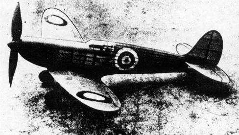
The Spitfire IX, shown here, is one of the prettiest of
that famous series of fighters.
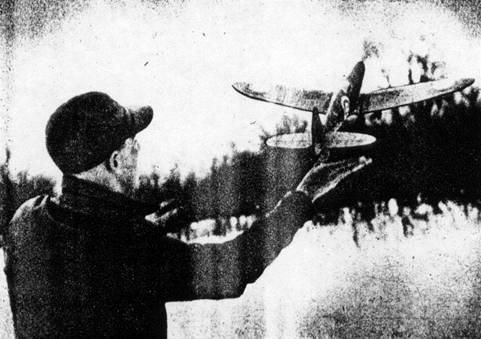
Climbs just like the real full‑scale ship. No design
changes were necessary for flying.
For our model, we have selected Spitfire IX which is representative of this remarkable brood of warriors. Simply built to attain lightness for good flying performance, this model Spitfire is nevertheless very attractive and is well worth the time and effort required for its construction. A word of caution, however ‑ select all balsa carefully to obtain light firm stock and remember especially to keep the tail as light as possible, for all excess weight behind the center of gravity must be balanced by ballast in the nose. Finally, work as accurately as possible using the plans and written instructions.
Easiest way to make an accurate fuselage of the Spitfire type is by the keel and bulkhead method. Cut the keels, top, bottom and two sides from 1/16" sheet which may well be sanded thinner to reduce weight. Incidentally, two of each bulkhead half as shown on the drawing are required. Assemble one set of them over the top and bottom keels which have been pinned to place over the fuselage side view. Slip a side keel into the proper notches and then, when this structure is dry, remove it from the jig and add the remaining bulkhead halves and keel. Stringers are medium grade 1/16" sq. strips and they may be sanded to reduce their weight. Using a razor blade that has been broken to a sharp point, cut notches in bulkheads that do not have them. Do this as the work proceeds so the stringers will be aligned exactly. Place stringers closest to the side keels first and always add them to similar positions of each side at one time to keep from pulling the structure out of line.
Between bulkheads C and D, where the wing fits in, curved pieces of 1/16" sheet cemented between the stringers in the rear anchor the rubber motor by cradling the bamboo pin that fits between them. (this is what is printed) At the cockpit, 1/32" sheet scraps are shaped to the form of the enclosure.
The extreme front of the nose is made from three pieces of 1/8" sheet that have been cemented together. As indicated by the broken lines, the center of the nose block is cut out to receive the nose plug, details of which are given. The front of this plug is a disc of 1/32" plywood while the back is laminations of 1/8" sheet. Drill the tiny hole for the prop shaft and then cement washers to either aide to fix the line of thrust.
Tall surfaces constructed in the following manner are both light and strong; both rudder and stabilizer are made similarly. Working directly over the plans, make complete frames using light 1/16" sheet parts for outlines and 1/16" sq. strips for spars and ribs. When dry, lift these flat frames from the plan and add very soft strips of 1/16" sq. stock to each side of each rib. To complete the construction, cut the ribs to a streamline shape.
It is required that the wing be of strong construction since the landing gear is attached to it. Ribs #1 and #3 are 1/16" sheet while the others are 1/32" stock. Sand them carefully to shape and cut the notches for spars. Spars and trailing edge pieces are cut from sheet and the leading edge is 1/8" sq. strips. Use pins to hold the various parts in place over the plans until the cement has set. Then join the halves with 1‑1/4" dihedral at each tip, adding center rib #I at that time. Next, fix the landing gear spar in place and finally, finish the whole wing structure by cutting and sanding the edges to conform to the airfoil shape.
Landing gear struts are fashioned from .040 diameter music wire. The wire is bent in such a manner that it may be attached to the wood structure as shown by the sketch. Be sure to make a right and left strut and then using needle and thread, sew them right to the ribs and spars. Apply several coats of cement to the thread wrappings and adjacent area. Incidentally, the rubber tubing covers for the scale appearance are not slipped on the struts until the model has been covered. By using a sharp razor blade and sand paper, wheels may easily be made from laminated discs of hard balsa. Washers or other bearings are best cemented to the sides so they will revolve nicely.
A VERY HARD balsa block or even white pine should be used for the propeller, the size of which is indicated on the drawing. Shape the blank as shown and drill a tiny hole for the shaft. Cut away the back face of the blades first, a bit of under camber is desirable. Now work away the front until the blades are of the proper thickness. Round the tips and reduce the depth of the hub. Use first rough and then fine sandpaper to finish the job and bring the blades into balance. Shape the spinner from a balsa block then notch it so it will fit over the hub, but do not attach it permanently until the prop shaft has been installed.
The various frames must be sanded to perfection before starting to cover; otherwise a neat, attractive job will not result. Colored tissue is recommended and it may be attached to the frames by banana oil or clear dope. For the fuselage, numerous small pieces, neatly lapped, will be required to avoid unsightly wrinkles. Use a separate section of paper when covering each side of wing panels and tail surfaces. Spray the covering lightly with water to tighten it and then fix the flying surfaces in a level position so they will not warp while drying,
Parts may now be assembled. Fit the wing securely into the recess in the fuselage; if the structures have been made with accuracy, the incidence will automatically be correct. A wing fillet pattern is given and two are to be cut from 1/32" sheet. They should fit neatly from fuselage to wing and may need a bit of alteration to fit your model exactly, Finish the area from wing to fuselage bottom with 1/16" sq. strips and cover with colored tissue. Cement the stabilizer and rudder in place, offsetting the latter a bit for a right turn. Small tissue fillets may be used to improve the appearance.
Add the few minor details and the ship is done. The cockpit enclosure is thin plastic such as cleaned photo film. Many will not want to undertake making a canopy with a compound curve and in this case, make It in two sections with straight longitudinal lines. However, some have been successful in forming these wind screens, turrets, etc. by heating a piece of very thin plastic in water until it starts to curl at the edges and then pressing it into a form of the correct shape or preferably stretching it over a carved wood die. Finish the landing gear next, using rubber tubing such as is found on electrical wiring and strips of paper wound about the tubing to simulate the structural details of the real ship's gear. Wheels should be painted before they are slipped on the axles where they are held by drops of solder. The covers that close the wing wells when the gear retracts are cut from 1/32" sheet and then covered with tissue to match the wing. Exhaust ports, tail wheel and other details that the builder may care to add are made from scraps of balsa and will go a long way in improving the ship's appearance. British Insignia may be cut from tissue and doped to the covering, or decals from the corner model shop will prove satisfactory. Naturally, all exposed wood parts should be colored.
Six strands of 1/8" flat, brown rubber carefully lubricated are used to power the miniature Spitfire. Hook the front of the loops to the propeller shaft and then drop the others through the fuselage where they are held by the removable bamboo pin. The model is now ready for its first test flights.
Before trying any flights, however, the position of the center of gravity must be checked. Balance the model by the wing tips and it should rest level or very slightly nose down. In all probability, if any corrective weight is required, it will be in the nose. Now glide the model, readjusting the weight slightly if it stalls or dives. Once satisfied with the glide, try short power flights offsetting the thrust line with thin slivers of wood between nose plug and nose to iron out a stall, down thrust, or on the right or left side to obtain the size circle desired. Flight performance in so small a scale model depends, of course, on, how carefully the model has been built and how well it is adjusted. But, if you have carefully built a light, accurate job, you will be rewarded with a consistent little performer, wonderful to behold in flight.
Scanned from November
1946
Air World
![]()
![]()
![]()
[ Home ] [ Previous Plan Pages ] [ Special
Things ] [ Earl Stahl Plans ]