The Plan Page
[ Home ] [ Previous Plan Pages ]
[ Special Things ] [ Earl Stahl Plans ]
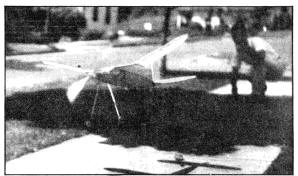
A Weight Rule Contest Model
Here Is A Reliable Contest Model of Three Ounces Per One Hundred Square Inches of Wing Area That Is Easy to Build
By EARL STAHL
A GOOD contest model need not only be capable of making long flights, but it should be stable, durable and sufficiently powerful for various conditions encountered in contests. In order to accomplish this the model must be stable, durable and sufficiently powerful to carry it to high altitudes.
Simplicity and flying ability are the key notes of this plane. Its construction is entirely conventional, and it is easy to adjust and fly. Its stability and power permit it to be flown in any weather.
The planes and instructions presented here are for building a plane to the new N.A.A. weight rule of three ounces per 100 square inches of wing area, but if a model of the old weight rule is desired it can be had by simply making the entire structure slightly lighter, reducing the power, and using a slightly larger propeller. This plane is an adaptation of just such a model.
Before starting construction it is advisable to make a full size plan. Since the drawing is one-fourth actual size, a full size construction can be made by enlarging four times with the aid of dividers. The fuselage top has three degrees of built-in incidence where the wing sets on, and zero degrees where the stabilizer is attached, so great care should be exercised to make this correct.
Fuselage
The whole fuselage is constructed of hard balsa. The two sides are constructed one over another in order that they be exactly alike. Join the sides together with 1/8 " square spacers and glue on the front formers. Bend the wire landing gear fitting, and secure it to the fuselage with thread at the position indicated. Cut the removable tail piece from the fuselage, and glue several laminations of 1/16" sheet into place to provide an anchor for the rear hook which is made from .040 or larger diameter wire. This hook incidentally should be protected by rubber tubing to prevent cutting the rubber motor, and it should have a hook on its end which will make it possible to lock it. Finally glue a piece of 1/8" sheet balsa to the front of the tail piece so it will fit snug to the rear of the fuselage, and keep the tail from turning when the motor is wound. The shaded parts of the fuselage, both front and rear, are filled with 1/16" sheet balsa for additional strength, and to provide a place to hold when the motor is being wound.
Wings and Empennage
The wing and tail surface construction is very similar except that the wing is built and covered in three separate pieces. Nineteen wing ribs are cut from 1/16" sheet balsa, and the medium hard spars attached. The tip ribs are trimmed to shape and size, and the tip outlines are cut from 1/8" sheet. The whole leading edge on the top is covered with 1/32" balsa as shown on the plans. The tail surfaces are constructed in a like manner except that they haven't any sheet balsa covering. Note that the tips of the stabilizer are 1/16" square bamboo. Be careful to have the rudder constructed so the flat side of the airfoil will be on the right of the model when the rudder is mounted.
Finish and Covering
Much of the plane's beauty depends on a neat, attractive covering job. The entire structure is sanded thoroughly to aid in making a good job. Cellophane is glued to the windows, and the individual units are covered with tissue, using banana oil as an adhesive. Select contrasting, visible colors such as red and yellow; black and yellow, or others, for this plane. When covering put adhesive on the extreme outlines of the frame only. If any wrinkles are present they can be removed more successfully if this procedure is followed. One exception should he noted however. On the under-surface of the wing the paper should be attached to each rib and spar to preserve the airfoils' shape. Water spray each piece and pin them to a flat surface to prevent warping. Every tissue-covered part is doped with two coats of light dope or banana oil.
The landing gear should now be finished. The struts are cut from 1/8" balsa (hard) and sanded to a streamlined shape. Hard wood wheels are attached by using .034 music wire axles which are bound to the struts with thread. The tops of the landing struts are bound to the protruding wire fittings of the fuselage. Be neat when binding anything with thread! This landing gear will prove very shock absorbent and prevent damage to the plane.
The various units may now be assembled. The outer Wing panels are raised at their tips to the indicated dihedral, and the joints are glued securely. This dihedral may seem excessive, but the plane will not climb in tight circles without it. The rudder is glued atop the stabilizer; the flat side parallel to the center rib. Next the unit, rudder and stabilizer, is glued to the tail piece ; the rudder's flat side being exactly parallel to the fuselage's center line. Glue small hooks to these two units, fuselage and tail piece, so they may be held together with rubber hands. A 1/8" flat rubber hand holds the wing on.
Propeller
Much of the model's success depends on the propeller. Cut the blank from hard balsa to the shape shown. A right hand propeller is cut. Some undercamber is cut into it. Round the tips, and the sand the prop well. Use four or five coats of dope for polish ; sanding lightly between coats. The nose plug is also made from hard balsa. The hole through the plug is drilled as the plans indicate so that the prop will pull slightly to the right. Washers are glued over the holes at either end to fix the line of thrust. A piece of 1/8" sheet is glued to the back of the plug so it will fit to the fuselage. The propeller shaft is bent from .040 wire or larger, and it should be covered with tubing and have a lock to prevent the rubber from slipping off. Several washers are placed between the nose plug and prop and the end of the wire shaft should be bent as shown so a winder can be attached, and so the end will fit in a hole protected by brass sheet to engage the free wheeling. A spring is made, and used as indicated to permit the propeller to spin when the motor is exhausted.
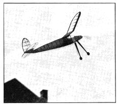
Flying
Many correctly built models never fly well because of poor adjustment, and many poorly built models fly well because of correct adjustment, so care should be exercised at this stage. Place an 18 strand motor in the fuselage. It should be 24 " long. Move the wing till a nice glide is had, and then wind the motor about 75 turns. It should climb slightly when launched and then glide down in right hand circles of about 70 feet in diameter. Once it glides well and in the proper size circle the power flight can be adjusted. It should climb swiftly to the right in circles of the same diameter as the glide. If a tendency to stall or "mush" is apparent, put a small block at the top of the nose plug to make the prop pull down. Change the block's size till the power flight is right. If it turns too sharply to the right under power put a small block at the right side of the nose plug, or reverse the procedure if the turn is too little. A small tab of stiff paper can be glued to the rudder if desired, to aid in adjusting.
Once the plane is flying well glue any adjustment blocks fast, and wind the motor tight for a real flight. The model shown was lost after an observed flight of nine minutes
Scanned from June 1938
Model Airplane News
![]()
[ Home ] [ Previous Plan Pages ] [ Special
Things ] [ Earl Stahl Plans ]