The Plan Page
[ Home ] [ Previous Plan Pages ]
[ Special Things ] [ Earl Stahl Plans ]
gt-hunter1@home.com
Complete Instructions and plans to build and fly
the Taylorcraft U. S. Army cooperation plane
by
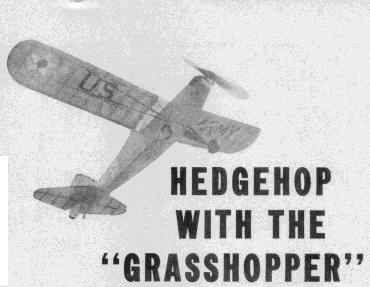
EARL STAHLAS THE ressult of the brilliant performance in the war games last summer the Army placed orders with the three largest manufacturers of lightplanes, Piper, Taylorcraft and Aeronca, for a fleet of "aerial jeeps", more popularly known as "grasshoppers".
Operating under simulated war conditions, the "grasshopper fleet" proved that lightplanes are indispensable in modern warfare. Flown by civilian pilots, these planes proved their adaptability for all kinds of observation work, personnel carrying, directing traffic and troop movements, even picking-up and delivering massages, maps, and materials in flight.
To further prove their value the "grasshoppers" repeatedly flew from seemingly impossible areas. In Louisiana army engineers prepared landing spots measuring a mere 400 ft. long and 100 ft. wide-and without considering wind direction. Obviously larger, faster planes could not use such bases, but these lightplanes in hands of skilled pilots made numerous takeoffs and landings. It was all in a day's work for pilots to land on highways, sometimes in open spaces between moving convoys, to complete a mission or possibly borrow a few gallons of gas. During maneuvers in Texas one pilot made several landings on the up-slope of a high mountain, then taxied around the gravel ledge rim, and took off on the down - slope. Of course there were a few accidents, but they were of a minor nature and quickly repaired. The most serious mishap resulted from a spin as a pilot cicled low so he could "Yoo-Hoo" to his girl friend.
"Grasshoppers" used in the war games were identical with ships available to civilians, all being converted tandem trainers powered by Continental 65 hp. engines. The only important additions were radio transmitters and receiver.
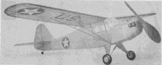
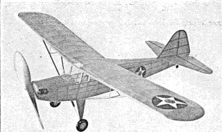
A small scale replica of the Army's latest airplane.
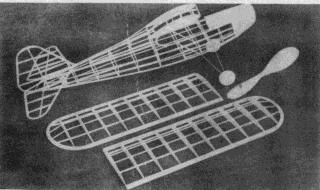
The structure is simple, light and strong
Parasol wing and long fuselage make it an excellent contest model.
For our model we have selected the Taylorcraft trainer, known in the Army as the O-57. This plane is similar in appearance, construction and performance to other tandem trainers on the market. Available with Continental, Lycoming or Franklin engines of 65 hp., the commercial version performs as follows: Top speed, 102 m.p.h.; landing speed, 35 m.p.h.; climb 600 ft. per min.; cruising range, 300 miles on 14 gallons of fuel.
The model has the same fine characteristics as the real ship: construction is easy and flight performance is matched only by attractiveness.
CONSTRUCTION. -Before starting, the fuselage plans should be joined: incidentally, if you do not want to mar your magazine, make tracings of the plans on semi-transparent paper.
First make the fuselage underframe, of 3/32" sq. balsa longerons and cross-pieces, indicated by light shading. Make two side frames, one atop the other for identity; the cement will probably cause them to stick together but they can be separated by a razor blade. When dry, invert the side frames over a complete top view plan and join with 3/32" sq. cross-pieces at the cabin. Next pull the backs together and add remaining cross-pieces in the rear. Crack longerons just in front of the cabin to pull sides together as shown. Check continually for correct alignment.
The various fuselage formers are shown; cut from each medium grade 1/16" sheet. Cut the notches shown and cement to place. Stringers are medium hard 1/16" sq. strips: fit in the notches and cement fast. From the cabin back stringers are cemented directly to the sides of the under frame. Center section ribs, cut from 1/16" sheet, are shown: two are needed with a third center cut as shown by the broken lines. Cement them to top longerons, against the inner edge leaving a 1/32" ledge on which to later rest the wing panels. Finish around the cabin by adding the wedge-shaped pieces. The curved back windows are cut from 1/16" sheet.
Cover the nose with soft 1/32" sheet, but before installing remove the crosspiece centers under the upper formers on the nose so they will not interfere with the rubber motor. Use the widest sheet available; cement it to the entire adjacent frame using pins and rubber bands to hold it in place until dry. Extreme front of the nose is a solid block or laminations, as shown. Roughly cut to shape, cut out hole for the nose plug, then cement to the fuselage front. When dry, cut the block to a smooth shape, then sand entire nose to shape.
Bend the two landing gear struts to shape and size shown from .040 music wire, attach to fuselage by neatly binding with thread and then applying several coats of cement. Join bottoms of the struts by soldering or with thread and cement. The 1/16" sheet fill-in can be cut and fitted but should not be attached until the fuselage is covered; the center struts likewise.
Make full size plans of the right and left wing halves so parts call be assembled directly over them. Using the patterns given, cut 18 of the regular and 2 of the tip ribs from soft 1/16" or 1/20" sheet. Pin all like ribs together and sand to uniformity, then cut the notches with accuracy. Pieces for the tips are cut from 1/8" sheet and assembled over the plan. Taper the 1/8" x 3/8" trailing edges before pinning to place over the plan. Pins keep the ribs in position. Spars are hard balsa; the uppers being 1/16" sq. while the lower are 3/32" sq. Leading edge is 1/8" x 1/4". Tilt the inner ribs a bit for correct dihedral. Cement all joints firmly, remove from plans and finish the leading edges and tips by trimming with a razor and sandpapering.
Tail surfaces come next; both stabilizer and rudder are of similar construction. Make complete frames using 1/16" sheet outlines, 1/16" x 1/8" strips for spars and 1/16" sq. pieces for ribs. When dry, remove frames from the jigs and add 1/16" sq. strips to every side of each rib. The ribs are later cut and sanded to streamline shape indicated. Taper leading and trailing edges to match the ribs.
To obtain fine flights from any flying scale model the propeller must be efficient. Select a hard block of proper dimensions and cut the blank to shape shown. Drill the tiny hole for the prop shaft, then carve a right - hand propeller, by cutting away the back, face of the blades until there is about 1/16" undercamber in each. Make each surface smooth and uniform with sandpaper. Blade thickness is then easily determined as the front is shaved away. Thin the blades as much as possible, still retaining desired strength. Round the tips like the prop shown in the photos. Carefully sand and balance the prop as the final operation. Several coats of light dope, if lightly sanded between each, will produce a smooth surface. A free - wheel gadget to improve glide should be attached to the front and a bearing to the back.
The nose plug is made from laminated squares of 1/8" sheet with a 1/32" plywood front. Test flights of the original model showed that several degrees of both right and down thrust are desirable, so drill the hole in this manner. Cement washers to the front and back to fix the thrust line.
COVERING AND ASSEMBLY - Before the frames are covered, they must be lightly but thoroughly sanded to remove all flaws and roughness. Colored tissue is used, banana oil or light dope is the adhesive. Cement cellophane to side windows before covering the fuselage. While performing the latter use numerous small pieces, carefully lapped, to avoid wrinkles; also cover the sheet balsa nose with tissue. Each side of each wing half, stabilizer and rudder requires a separate piece of tissue, tips, etc., require individual pieces, too. Lightly spray all covered parts with water to tighten the covering - do not, however apply any clear dope until later.
Prepare to assemble parts by completing the fuselage. Cut a windshield pattern from writing paper by the trial and error method; note the windshield extends over the center section to the first crossmember. Once the pattern fits perfectly cut from celluloid and attach with cement. The landing gear fill-in was made previously and is cemented to the wires. Cover the whole landing gear with tissue. The center landing struts are rounded bamboo splints with streamline balsa covers at the top, representing shock absorber covers. Cement the bamboo to the bottom of the struts but not the top so they can spring apart. Wheels can be made from laminated discs of balsa or may be purchased. Cement bearings to the sides of the wheels so they will revolve smoothly then place on the axles and hold in place with a drop of solder.
Care must be exercised when assembling the surfaces to the fuselage to keep everything in perfect alignment. First cemet stabilizer to place; it is parallel to the work bench. A tissue fillet is placed from fuselage to stabilizer before the rudder is set in position. Off-set the rudder about 1/16" for a right circle glide. Wing tips must be dihedraled about 1-1/2" for proper stability. Be sure to attach the wings firmly. Wing struts are shown; assemble and color before cementing to position. The entire model is now given one or two coats of clear dope.
There are numerous minor details added to improve appearance. For the more ambitious builder the four - cylinder engine offers plenty of possibilities for detail. Insignia, letters, control surface outlines, etc., etc., are all made with colored tissue. Tail wheel and similar parts are made from balsa scraps. Additional details can be found on photos of the big "grasshoppers" for those interested in reproducing every item. Naturally any uncolored wood parts should be doped to match the color scheme.
Bend the propeller shaft from .040 music wire. Slip the nose plug, several washers and prop on the shaft in that order, then bend the shaft end as required for the free-wheeler.
FLYING - Depending on the finished weight of the model, ten or twelve strands of 1/8" brown rubber is required for power. Lubricate the strands, hook them on the prop shaft and then drop the other end through the fuselage. As shown, a bamboo pin holds the motor in the rear. If necessary, remove a small section of covering to aid in getting the motor in position.
The Taylorcraft "grasshopper" should balance at a point about 1/2 back along the wing chord. Add weight to the nose if necessary to obtain this balance, since only minor, adjustments are made by warping tail surfaces. Glide the model over deep grass making any further adjustments for a good glide.
Power flight adjustments are made by off-setting the thrust line. Start with just a few turns - then use more power as justified. Placing a sliver of wood between the tip of the nose plug and the nose tilts the thrust line down, helping to iron out stalls under power. Right or left thrust helps to control the circles.
Once the "bugs" that usually show up in first tests are eliminated, use a mechanical winder to get maximum turns and power from the rubber motor. Take care where you launch your "grasshopper," for the top of a tree or the side of a building is hardly a suitable landing field; you have quite an investment of time and effort in your Taylorcraft - protect it with good judgment.
VICTORY
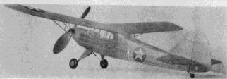
A large high pitch prop gives it. long duration
Scanned from
April 1942
![]()
![]()
![]()
![]()
[ Home ] [ Previous Plan Pages ] [ Special
Things ] [ Earl Stahl Plans ]