The Plan Page
[ Home ] [ Previous Plan Pages ]
[ Special Things ] [ Earl Stahl Plans ]
gt-hunter1@home.com
AS a weapon of war the glider has come of age. First successfully used by Germans in the invasion of Crete, these motorless carriers of men and munitions more recently figured prominently in the Allied conquest of Sicily.
Towed to a point near their destination by large twin‑engine transports which likewise carry supplies and even paratroopers, the glider cuts free to make a stealthy approach. Virtues of the glider are numerous: it lands lightly in small space and when necessary even "crash lands" without serious damage to crew or cargo. It is inexpensively and quickly built, thus is expendable. Because of a “whispering" approach, it provides a measure of surprise.
Aside from the glider's combat importance, it offers great new possibilities in air transport. In England recently a glider descended through the cloud ceiling to make a smooth, graceful landing on an airfield. Utilizing the "sky-train" technique it had just flown across the Atlantic. The glider was towed by a Douglas C-47 transport (similar to the commercial DC-3) and the 3,500 mile journey was completed in 28 hours. (See November, 1943, issue.)
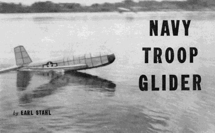
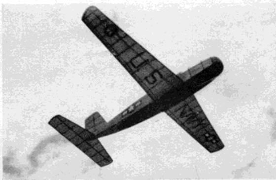
Recognizing its importance in aggressive warfare, the U.S. Navy has developed a unique and efficient glider; it is amphibious, landing either on land or water. As a troop transport it is capable of carrying twelve fully equipped men. Construction is entirely of plastic bonded plywood. These ships are built by Allied Aviation and Bristol Aero and, of course, performance data and specifications are restricted.
Our model is a faithful reproduction of the prototype. Of simple construction it is nevertheless a capable flyer. When hand‑ or tow‑line launched the little ship floats down in an easy curve to a smooth landing.
CONSTRUCTION: The manner of construction is entirely conventional; the model can be built quickly and easily. While balsa was largely employed on the original, white pine, spruce or bass can be substituted without impairing flying qualities. When it is necessary to substitute these slightly heavier woods the cross-section size can be reduced since they are also stronger. Regular model airplane cement is used in either case; however, regardless of the wood being used, make the structure as accurate as possible and cement each joint firmly.
The fuselage consists of a simple rectangular frame about which the shape giving formers and stringers are assembled. Join the plans together and build the two sides of the underframe (shaded) directly over it make one atop the other so they will be identical. Erect the sides over the top view and join them with cross pieces; check the structure frequently for correct alignment. Formers are shown full size and they are cut from the sheet; a number of them are identical so be sure to make any extra required. A few have no notches and when this is true, stringers are cemented right to their sides. Attach the formers to their respective places and then add the fairing stringers. It will be noticed that the bottom "keel" is deeper than 1/16" and thus it should be cut to shape from sheet stock. Formers 1, 2 and 3 are for windshield supports, made from bamboo bent over a soldering iron or candle flame.
Correct angular placement of the wing and stabilizer is important. From sheet cut required pieces for these mountings so they will be exactly as shown. The wing slot is large enough so it can be slid through for dismounting.
Roughly shape the nose from balsa or other light wood, then cement it fast and finish to exact size and shape. Launching hooks are shown; they are bent from .040 music wire. Securely fix them to place by binding with thread.
Light, non-warping construction is used for the tail surfaces. Both rudder and stabilizer are similar; the latter is in one piece despite the half‑plan shown. Make a flat frame for each using 1/16" sheet for outlines and 1/16" sq. for spars and ribs. When these frames are dry add 1/16" sq. strips to each side of each rib. These are then cut streamline and the edges trimmed to blend with the crossection curvature.
Only a right wing plan is included on the plan, so a left one must be drawn. Construction is conventional and easy. Ribs are 1/32" sheet; the spars are cut to shape shown from material indicated. Wing tips are 1/8" sheet. Make two of each part, carefully shaping them correctly. Assemble the wing in two parts working right over full size plans: pins will aid in holding the parts in place until cement hardens. Once assembled, join the halves with 2-1/2" dihedral at each tip. Taper leading and trailing edges to conform to the airfoil shape and smooth off the tips.
Before the frames are covered they should be worked over with fine sandpaper. Sand each port of the structure lightly but thoroughly to remove all roughness and flaws.
Colored tissue is used for covering since it is both attractive and practical. Banana oil or light, clear dope serves well as the adhesive to stick the tissue to the frames. Numerous small sections of paper will be required to make a
Magazine was not complete
Scanned
from January, 1944
Model Airplane News
![]()
![]()
![]()
![]()
[ Home ] [ Previous Plan Pages ] [ Special
Things ] [ Earl Stahl Plans ]