 |
 |
 |
 |
The Plan Page
[ Home ] [ Previous Plan Pages ]
[ Special Things ] [ Earl Stahl Plans ]
gt-hunter1@home.com
|
|
|
|
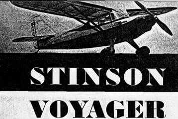
by EARL STAHL
This scale job has CO2
power
you spend your
time flying, not fussing
Among the fastest selling planes of the day are the well known Stinson Voyager and Flying Station Wagon. Reasons for this extreme popularity are numerous. Of all the larger personal planes they are among the least expensive to purchase and operate. Further, they can be flown with ease.
But probably the most important is their wide usefulness. With the ability to carry 4 passengers in comfort, or a pilot and a sizable quantity of cargo, they serve as family plane of business craft of great utility. As compared with some of its competitors, a Stinson is fairly slow since it cruises at close to 120 mph. Yet this is somewhat offset by the fact that it can be flown by pilots of limited experience into and out of any field that can be called an airport. This is not always possible, of course, for planes of higher stalling speeds and more qualities. In this connection the writer can volunteer the opinion, after flying Voyagers, that just anyone who can fly any other type of plane safely can master the Stinson with ease.
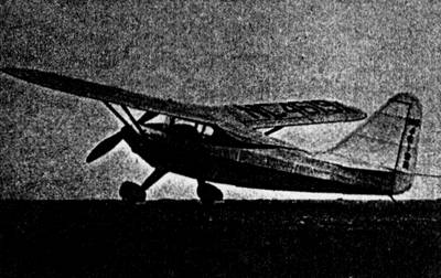
Our model is of the latest Stinson which features larger tail surfaces to enhance the plane's inherent stability. The Voyager's configuration lends itself well to the requirements of a good model, particularly one powered by an expansion-type reciprocating engine such as this one has. We used one of the Herkimer OK CO2 engines in the test ship and were highly pleased with the results.
Light weight, so long as it is consistent with strength requirements, is always important whether it be in the creation of a giant transport or bomber, or a mere model, and our Voyager is no exception. Since the carbon Dioxide capsule and motor unit weigh considerable, the airframe must be fabricated with extreme care to keep the gross weight close to 5 oz.
Construction of the model is really quite simple and no difficulty should be experienced if drawings are studied
and the text read before starting. Balsa wood is used throughout and regular model airplane cement is the adhesive. You will want a model that is a treat to behold whether it is on the shelf or on the wing, so assure this by putting your best effort into the task.
Since assembly of most parts can be accomplished more easily over full size drawings, the magazine page layout should be doubled. This is accomplished by stepping off each dimension twice using dividers. One-half inch grid is imposed over many of the curved parts to ease the job of enlarging them. (See articles on "Scaling Plans," Oct. and Nov. 1947, issues of M.A.N.)
Construction is logically begun with the fuselage. It consists of an underframe about which formers and stringers are mounted to derive the scale appearance. Build the 2 sides of the underframe first from 3/32" sq. strips using the plan as an assembly jig. (The frame is shown lightly shaded) assemble these sides one atop the other and then, when dry, separate and rejoin them with 3/32" sq. members as indicated by top view. The mount for the stabilizer and rudder is shown in perspective and it must be placed with accuracy; material for it is hard 3/32" sheet cut into strips of the right width. Formers are cut from 1/16" sheet balsa and they are cemented to their respective positions.
Since the wing's centersection becomes an integral part of the fuselage, it should be assembled at this time and then attached to the fuselage. Just forward of bulkhead A is a 1/8" plywood bulkhead for mounting the engine; its shape is identical to A's. Drill mounting holes for the engine and firmly cement No. 3-56 nuts to the backs of the holes to enable installation and removal of the engine with greatest ease; cement the plywood mount firmly to place. Stringers are 1/16" sq. strips of hard balsa and they are fitted into the notches provided. Cover the shaded portions of the nose with 1/32" thick planks varying the width of each as dictated by the curvature of the area being covered. An alternate method is to inlay sections of very soft balsa between the stringers and then trim the excess thickness to the shape shown. The nose block is hollowed to fit over the engine and it has a hole in the center for the shaft, 1 in the left side for the cylinder head, and 2 on the front to represent intake louvers of the real ship. The nose block can be cemented lightly to place, as there should be little need to get to the engine.
On the original model the cartridge holder was attached to a piece of 1/8" x 3/8" hard balsa by binding one side of the holder tightly to the wood using thread and cement. This unit was the mounted vertically within the fuselage at the position shown; secure it firmly to the adjacent structure.
The landing gear consists of 2 wire struts an each side with a wood filler between. Bend the struts from .040" diameter music wire as shown. They are bound with thread to the fuselage and the ends soldered together. The filler is balsa which tapers in thickness from 1/8" at the top to 1/16" at bottom: it is streamline in crossection. Silk or tissue is used to hold the filler in place by covering the whole undercarriage wire and wood together. Wheels may be made from laminated discs of balsa and they should have washers or other bearing surface fixed to them to permit free turning. Wheel pants look good but do not contribute to the plane's flying qualities so are not recommended.
Make full size plans of the right and left wing panels so parts can be assembled over them. Using the section shown, make a pattern for the ribs and then cut them from 1/16" balsa sheet. Sand the ribs uniform and cut the notches for the spars which are hard strips of 3/32" sq. The leading edge is 1/8" x 1/4" while the trailing edge is 1/8" x 3/8"; tip pieces are cut from 1/8" sheet. Tilt the inner ribs a bit for a satisfactory joint when the dihedral is added. After the cement has set, remove the wings from the plans and trim the edges to conform to the airfoil shape; then sand the structures smooth.
Tail surfaces come next and both stabilizer and rudder are of like construction. Make complete frames using 1/16" sheet for the outlines and 1/16" sq. strips for the spars and ribs. When these structures are dry, add 1/16" sq. strips to top and bottom of each rib. The ribs are later cut and sanded to the streamline shape shown.
Before frames are covered they must be thoroughly sanded to prepare for a good job. Colored tissue is used and it is attached to the frames with banana oil. Install cellophane side windows before starting to cover the fuselage. While covering the fuselage and other compound curve parts, use many sections of tissue, carefully lapped, as will be required to prevent wrinkles. Once covered, all parts should be lightly sprayed with water to tighten the tissue but no dope is applied until the parts are assembled.
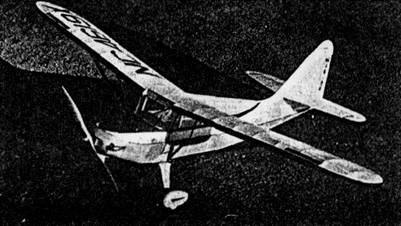
The various units may now be assembled. The front windshield is thin celluloid and a paper pattern for it must be made by the cut and try method. Set the stabilizer atop the mount in the position shown and firmly cement it fast. Then place the rudder, offsetting the leading edge to the left slightly for a right turn in the glide. Wings have 1-3/4" dihedral at each tip for proper stability. Wing struts are shown by broken lines over the wing drawing and they are made from 3/32" thick balsa; crossectional shape is of course streamline. The entire model is now given 1 or 2 coats of clear dope.
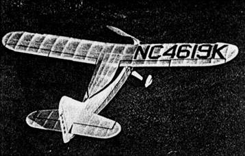
Numerous minor details may be added to improve the appearance without impairing the flying qualities. On the original model trim details are colored tissue and the decorations, license numbers, control surface outlines, etc., are realistically represented. Items such as cowl grill, carburetor air intake, tail wheel, foot step and the like are easily represented by scraps of bamboo and balsa. Additional details may be found on photos of the real ships for those interested in reproducing greater realism.
Commercial propellers are available or one may be carved from white pine to the specifications given. With care a more satisfactory prop can probably be made by the builder and every model maker should practice the nearly forgotten art of prop carving.
To prepare the model for flying, a cartridge is installed by slipping it within the fuselage opening beside the holder; it is then maneuvered within the holder and is ready for discharge. A cover hatch is shown by broken lines; it is optional and hardly worth while.
In flying any model, sound judgment is the greatest assurance of success. Keep this in mind and strive to get the maximum results from your efforts. Before gliding the model, check the center of gravity position by balancing it at about the 25% chord position of the wing. It should rest level; in the event it doesn't, add lead ballast at the farthermost nose or tail position. Glides should be smooth descents from shoulder height and any possible erratic performance such as stalling or diving should be corrected by further weight adjustment. First power flights should be with reduced power resulting from not launching the model until some of the energy of the capsule is expended. Power output of the motor can also be reduced by slightly unscrewing the cylinder. Try it 1/16 of a turn at a time until the power is suitably reduced. Minor adjustments may be made by warping the flying surfaces, wing, stabilizer or rudder. In the event glides are satisfactory but power flights have a stalling tendency, tilt the thrust line down slightly by inserting a small washer or 2 under the top lug of the engine.
The model Voyager is a trim little ship, keep in line and fleet in flight. It hasn't the usefulness of its prototype but it is just as much fun to fly!
Scanned
from June, 1948
Model Airplane News
![]()
![]()
[ Home ] [ Previous Plan Pages ] [ Special
Things ] [ Earl Stahl Plans ]