The Plan Page
[ Home ] [ Previous Plan Pages ]
[ Special Things ] [ Earl Stahl Plans ]
gt-hunter1@home.com
Grumman Wildcat
BY EARL STAHL
You'll enjoy building this F4F-3 used by marines at Wake Island.
She's tops for performance.STANDARD fighter of the U. S. navy and marines is the Grumman Wildcat F4F-3. A single-seat pursuit of midwing design, it is sturdily built and possesses a high degree of maneuverability. It is primarily designed as a shipboard fighter.
Like most military planes, performance figures have been restricted. However, these details of the Grumman G-36, a similar ship used by the RAF fleet air arm, have been released: A twin Wasp engine of 1,200 h.p. affords a top speed of 330 m.p.h. Cruising speed is 300 m.p.h., and the landing speed is less than 70. Climb is more than 3.000 feet per minute, while the cruising range is 1,150 miles.
Every flying scale fan will want a model of this outstanding plane for his fleet. Simply built to conserve materials and attain lightness for best flying ability, the little ship has proved to be a stable, consistent performer. In spite of the bulky, heavy appearance of the real ship's design, the model has a snappy, tight-spiraling climb and easy glide. Needless to say, the model's ability to withstand abuse is inherent.
The pages of plans are drawn full size, and they are intended to be joined together. It is best to make tracings of the important parts and thus the magazine will be kept intact. All balsa wood should be selected carefully to assure a sturdy, light structure; make all frames accurately and, finally, cement each joint firmly.
CONSTRUCTION
The keel and bulkhead method of construction is employed for the fuselage. Notice that the rudder is built right with the fuselage; it is in reality a part of the top keel. Cut the various parts of the four keels - top, bottom and two sides - from sheet as shown. Bulkheads also are sheet, and only the notches shown are cut out; others are marked to be cut later as needed. Assemble over the fuselage plans by pinning the top and bottom keels into place. Half of the bulkheads are cemented into position and a side keel attached. Now remove this structure from the plan and add the remaining bulkheads and side keel. Stringers are of firm 1/16" square stock. Attach those closest the side keel first and onto both sides at the same time to keep from distorting the frame. Cut notches as required for a neat, accurate job. Where the wing joins the fuselage, 1/16" thick rib-like pieces are cemented to the bulkheads and side keel as shown on the side view.
The extreme front of the nose is made with laminated disks of 1/8" sheet cut to the shape of Bulkhead A. Remove the centers of the two front disks so that a dummy motor can be installed if desired. Trim to shape with a razor blade, then sand to complete the nose. Details of the nose plug are given and it likewise is made from laminated disks of hard 1/8" sheet. Cement the back portion within the cowl; the front section is removable to permit stretching of the rubber motor for winding. As shown, a hole is drilled for the prop shaft and washers are cemented to the front and back to fix the line of thrust.
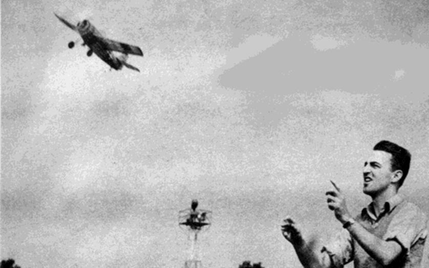
 Can you tell it from the big brother? The Wildcat includes large tail area, ample dihedral, which are necessary for all successful flying scale models. |
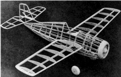 Designer Stahl stresses simple framework construction for good flying qualities. You'll find this job no harder to build than a square-sides boxcar. |
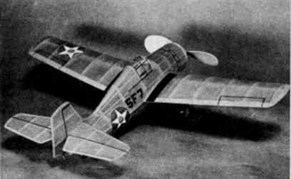
Under view and tuck-up wheels for a Jap
view of the Wildcat.
Note the well proportioned prop with freewheeling,
for astounding performance.
Curved sections of 1/32" sheet are fitted from Bulkhead D to the top stringers to form the cockpit shape. In the rear, small blocks of hard 3/32"sheet are cemented between the stringers to cradle the removable bamboo pin that holds the rubber motor.
A special bulkhead, to which the landing gear is attached, is cut in two pieces from hard 1/16" sheet. Details of the landing unit are given. Bend the main landing strut from .040 music wire and then, using needle and thread, sew it to the landing gear bulkhead. Other parts of the gear are not completed until later; however, the wheels may be made from laminated disks of 1/8" sheet at this time. They should have washers or bearings cemented to the sides so they will revolve smoothly.
To assure the correct incidence of the stabilizer, a notch is provided in the rudder into which each stabilizer half is fitted. Construction of the tail-surface parts is so simple that little need be said. Simply build two flat frames of 1/16" thick stock over the plans and then add soft 1/16" pieces to the sides of each rib and shape as shown in the sketch. Rudder ribs are finished in this manner, too.
Construction of the wing is next. It is made in two parts and it will be necessary to make a right wing plan. Cut the required number of ribs from medium grade 1/32" sheet. Sand them carefully to exact shape and size and cut the notches for the spar. Spar and leading edge pieces are cut from sheet stock as indicated, and the trailing edge is a tapered strip of 1/8 x 3/8". Tips are cut from 3/32" sheet. Assemble the parts right over the plans, using pins to hold in place until the cement has set. Finish the parts by cutting and sanding the tips and edges to conform to the airfoil's shape.
For any model to fly well it must have an efficient propeller. A 6" diameter prop is recommended for the model Wildcat. Select a hard balsa (or white pine) block of the indicated size and shape the blank as shown. Drill the hole for the shaft and then carve a right‑hand airscrew; work carefully and do a good job. Round the tips of the blades and reduce the thickness of the hub - examine photos of the original model for further details. Use rough and then fine sandpaper to finish and balance the blades. Several coats of light dope with sanding between each will harden and smooth the surface. A freewheel gadget of some sort will improve the glide if attached to the prop, thus permitting it to spin free once the motor is exhausted.
Make a propeller shaft from .040 music wire. Slip the nose plug, several washers, and the propeller on in the order given. Bend the end of the shaft to suit the freewheeler used, but if none is being used, bend the end at a right angle and cement to the hub.
Prepare the frames for covering by working over the entire structure with fine sandpaper. The author likes to sand the bulkheads to a scalloped shape so only the stringers will touch the covering; this makes a neater job. Regular colored tissue is used and thin banana oil or dope is the adhesive. Use a separate piece of tissue for each side of each wing half, rudder and stabilizer. Wing tips and the like require individual pieces, too. When covering the fuselage, it will be necessary to use numerous small pieces to work around the curves without wrinkles - this is especially true where the fuselage flows into the rudder. Individual pieces of tissue must be lapped carefully to the next piece for best results. Spray the covered parts lightly with water to tighten the tissue; the flying surfaces should be held in a level position so they will not warp. Clear dope is not applied until the parts have been assembled.
Assemble your model Wildcat in this manner: Cockpit details are finished first. Before cutting the thin celluloid, paper patterns of the parts should be made to fit exactly; use the cut-and-try method to accomplish this. Cement the celluloid to place, being careful not to smear adhesive on the enclosure. Structural details are represented by tissue strips doped to place. If the structures have been made with accuracy, wing and stabilizer incidence will he correct. Cement the stabilizer halves to the slot in the rudder, being careful to align them perfectly. End ribs of each wing half are butted against the sheet filler on the fuselage; make these joints strong. Dihedral of each wing is one inch. One or two coats of thin dope can now be brushed on the entire model.
Addition of the various minor details completes the job. Slip rubber tubing (or any other kind) of the correct diameter over the main landing gear struts. Wells into which the undercarriage retracts are represented by black tissue doped to the covering. The four V‑shaped auxiliary parts of the landing unit are for scale appearance only, and are made from rounded pieces of bamboo. They are attached to the fuselage, but are not secured to the main strut, thus permitting it to spring freely and absorb shock. Wheels are painted before being fixed to the axles by washers soldered to the ends. Thin sheet balsa covers colored to match the fuselage may be added. The tail wheel and similar items may be made from scraps. Cowling details, flying surface outlines and even insignia may be made from colored tissue. However, the new decal insignia are neat in appearance and very convenient to use. The builder desiring most detail can install a dummy motor within the cowl without harming the flying ability. Naturally, the propeller and similar wood parts should be doped to match the color scheme.
FLYING
About six strands (three loops) of 1/8" flat brown rubber will be needed to power your flying Wildcat. It is best to lubricate the motor before placing it within the fuselage. Attach the strands to the prop shaft and then drop the other ends through the nose; they are held by a thin bamboo pin in the rear.
The Grumman Wildcat should be made to balance at a point about halfway back from the leading edge. Add weight to the nose or tail as required to obtain this balance, as only minor adjustments are made by warping the tail surfaces. Glide the model over soft grass, making any further adjustments for a good glide.
Powerflight adjustments are made by offsetting the thrust line. Start with just a few turns, and then use more as flights improve. By placing a sliver of wood between the nose plug and nose, the thrust line will be tilted down, thus helping to iron out a stall while under power. Right or left thrust will make the model circle as desired.
Once all the "bugs" that usually show up in the first tests are eliminated, use a mechanical winder to get maximum power and turns from the motor. The author's test model in spite of its small size and light weight (1.2 ounces complete), flies as realistically as the prototype.
Scanned from November 1942
Air Trails Pictorial
![]()
![]()
![]()
![]()
[ Home ] [ Previous Plan Pages ] [ Special
Things ] [ Earl Stahl Plans ]