|
Korda's Dethermalizer Proving that out-of-sight flights can be stopped, this
greatest of all Korda
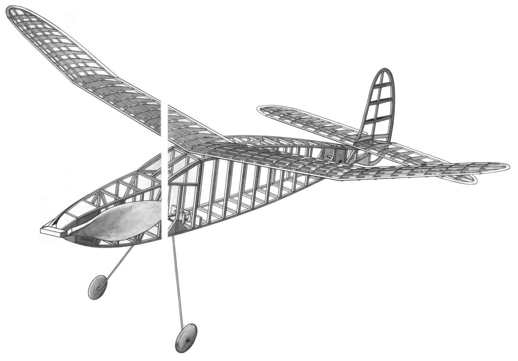
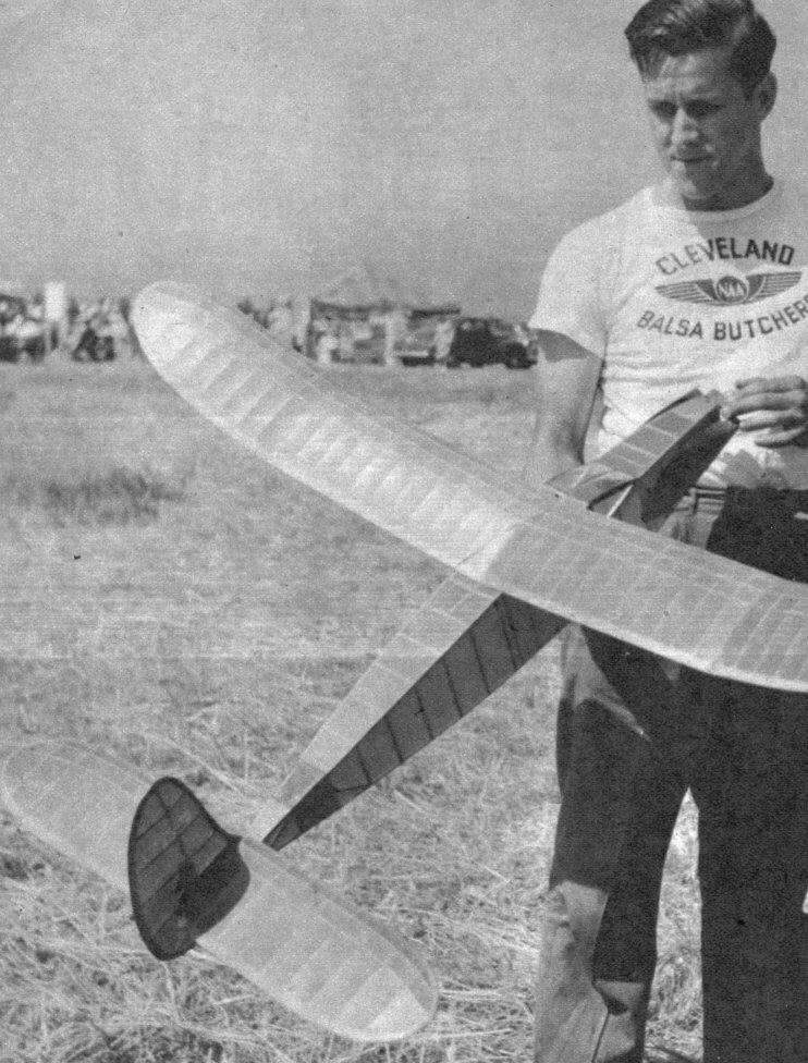
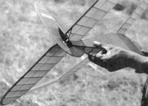
THE main feature of this ship is the device, nicknamed "dethermalizer," which is used to bring the ship down, at a predetermined time, in case it should hit a thermal and go out of sight of the timekeeper. Proof of its effectiveness was shown at the Nationals this year. Of five out-of-sight flights, only two were recovered at the end of the flight, and these two were the ones using the dethermalizers. On one flight we got stuck on a dead-end road at the end of five minutes and were watching the ship float out of sight about a thousand feet high and about half a mile away when the dethermalizer, which was set at six minutes, kicked in. The ship spiraled in and was on the ground at eight minutes. Without the dethermalizer, it would have been lost. Wing. Start the wing by laying out the two center panels and one tip first. Cement all the ribs in the center panels, allow to dry. To make the tapered ribs for the tip sections, cut a standard rib short enough to fit, then lay the rib template on top, keeping the V's, that the leading edge fits in, together. Leave the rib 1/8" high at the rear, to fit the trailing edge, and cut along the top of the template. In this way you can make a fairly accurate wing, but as you get to the last four tip ribs you will have to sand a little off the bottom of the ribs where the first spar runs through. Leave one center panel pinned down and block up the other center panel 3-1/4" -- the tip section is blocked up 3". Cement in the gussets at the dihedral joints and allow to dry. Next cement in the 1/16 x 1/8" spars on top of the center panels; the spars for the tip sections taper from 1/16 x 1/8 to 1/16" square at the very tip. When dry, glue in bottom spars, then lay out final tip and glue onto rest of wing, blocking up the center of the wing 3-1/4". Cover the wing with the paper grain running the length of the wing. Water-spray the wing lightly and allow to dry. Make sure that the warps are taken out of the wing as it dries, then finish by giving it four thin coats of dope. Tail. The stabilizer is made in about the same way as the wing, but the small balsa parts that go in the V section, where the rudder passes through, will have to be fitted and sanded to shape.Rudder. Lay out the rudder outline on the plans and then glue on the 1/16 x 1/8" cap strips. The slight bend in them can be accomplished by drawing them between your fingernails. After drying, glue the strips on the opposite side and fill in between with scraps of balsa to prevent crushing.Prop. Carve the prop from 1-3/4 x 2-1/4 x 18" medium balsa block. Lay out the top and side views as shown on the plans, and start by carving out the inside of the blade first, and semifinish with medium sandpaper. Leave 1/8" undercamber at the widest section of the blade. Next carve the outside of the blade. Leave the blade about 3/16" thick, at a point 2-1/2" from the prop shaft, to 3/32" at the tip. Finish sanding the whole prop with fine sandpaper and give it four thin coats of clear dope, sanding in between. The two blades are then cut free of the hub, being sure to keep them perfectly square and flat, and then are glued lightly to another hub that is made of two sheets of 1/8" or 5/32" flat hard balsa.Glue these together to form an extra-strong hub needed to take the terrific beating a folding prop is subject to. The next step is to make the hinge. Use 1/32" tempered brass or copper and cut to the shape shown on the plans. Roll each end over a piece of .032" wire, making it a snug fit. Then take the wire out and slide a strip of 1/32" bamboo through each end and solder the rolled ends securely. Re very careful when making the hinge or the finished prop will not fold properly. The slight angles that the ends are rolled at cause the blade to fold flat against the body, but not parallel with each other. In order to make parallel, twist each end of the hinge slightly, in the same direction as the pitch of the blade. Slide a 3-1/4" piece of .032" wire through each end and bend to fit the inside and outside of the blades. Bend all four ends about 3/16" from the end and press into the wood. Glue the hinge firmly to the back of the hub and also glue on the fitting on the front of the hub, keeping the prop-shaft hole lined up. The wire running to each blade should also be glued, and the whole prop allowed to dry thoroughly. When dry, cut the blades free of the hub and check to make sure the blades fold flat and parallel. Bind each end of the hub and blades with strong button thread and apply several coats of cement. Make a prop shaft of 1/16" music wire by bending the end that holds the bobbin first, run it through the nose block and the prop, using three or four washers in between. Make a loop for the winder, then over and down into the guide hole in the hub. Wrap thin copper wire around the base of the winder loop and solder, and finish up by twisting on a spring. Finish the prop details by inserting the nose plug into the body and folding the blades against the body. Hold the blades carefully in place, pull out the nose plug and mark the spot where the prop-shaft stop is and drive a flat-headed 3/4" wood screw into the block at this point. Fuselage. Lay out two sides, one on top of the other, and allow to dry completely. Next split them apart with a razor and pin the two sides upside down on the plans, using the uprights and center line as guides. Glue in the five dihedral cross braces just behind the windshield and also five 1/8" square cross braces, of the same length, on the bottom. When this has dried, pin the rear ends of the body together and glue.Glue in the two cross braces in the nose at the same time and allow to dry. Then take the fuselage off the plans and glue in all the rest of the cross braces. The sizes are shown in the plans. The landing gear is glued in the body between a double layer of 1/8" flat gussets. One layer is glued to the longerons and uprights, while the second layer is glued to the first ones and also to the 1/32" pine sheet that holds the landing-gear wire. The plug part of the nose block is made of 1/4" pine and the rest of a block of hard balsa. Drill a 1/8" hole through the center and press in and glue the two brass bearings. Be sure to put in about three degrees down and one degree right side thrust. Timer. Take a regular Austin air timer and remove the fiber and contact points. Substitute a thin piece of aluminum for a cover. The timer -- minus the needle valve and lick washer -- is laid inside the fuselage, with the bottom against the landing gear. Glue a 1/8 x 7/8" sheet of balsa across the body -- marked No. 1. This piece has a 1/4" hole in the center for the plunger rod to pass through. Use a piece of 1/8" fiat balsa to fill in between the 1/8 x 7/8" strip of balsa and the upright that runs behind the windshield. Next glue two 1/8 x 3/8" pieces of balsa, marked No. 2, on edge, on back of the landing gear running up each side of the timer. Glue another 1/8 x 3/8" piece, No. 3, across the top of timer. Glue in a piece of 1/8" square hard, No. 4, running across the top of the timer and between the two uprights at the back of the windshield.Finish by gluing in two 1/8" square pieces, No. 5, along each side of the timer. Use plenty of cement to hold the timer in. Make a small loop on one end of a piece of .032" wire and lock it between the lock nut and needle valve of the timer and run along the bottom of the fuselage -- on the inside -- and back to the left side, looking at the plane from the rear. The actual length, when the timer is closed, should be 3/16, short of the flap lock. Before attempting to use the flap, pin it down in closed position and completely adjust the ship for glide and climb. Then run a single strand of 1/32" square rubber from the hook on the bottom of trailing edge of the stabilizer to the aluminum flap lock and set the timer to kick the flap off at about 1-1/2 minutes. Allow the flap to go over only about 1/4" at first and then increase it 1/8" at a time, until enough spiral to bring the ship down out of any thermal is obtained. The amount the flap can move is controlled by a 1/8 x 1/4" block which is glued in the V of the stabilizer. Scanned From February, 1942
|
||||