|
Flying Wings By Henry Cole FLYING WINGS REPRESENT THE THEORETICAL ULTIMATE IN
AIRCRAFT DESIGN.
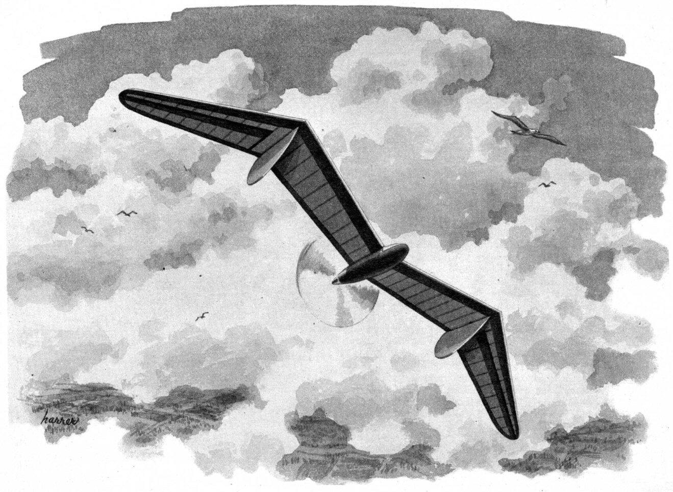
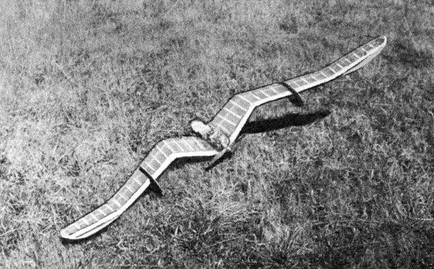
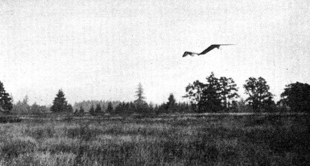
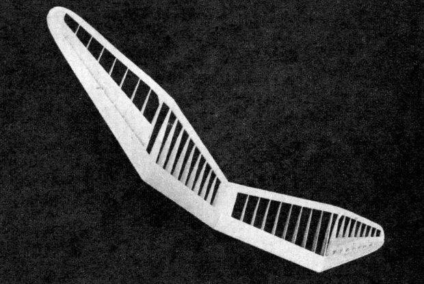
The absence of fuselage and tail surfaces makes the flying wing aerodynamically and structurally superior to conventional types of aircraft. Nevertheless, despite these advantages, there have been few successful tailless designs -- and yet birds prove that high performance is attainable. The most well-known among man-made tailless airplanes are Waterman's Arrowbile and, more recently, the Northrop Flying Wing. The development of these planes and the remarkable flights of the birds indicate that further experiment will pay great dividends. Presented in this article are three basic designs which were developed through glider experiments and bird observation. The many problems which come up in building a tailless model will be discussed so that the reader will have an insight into tailless design and avoid many of the pitfalls of experimentation. Design No. 1 was selected from a number of balsa test gliders because it showed the greatest stability and could be made to circle very tightly without spiraling in. This enables the model to stay in the slightest updraft and ride the wind like the birds, a great advantage over normal craft. After thorough glider tests, the design was scaled up to Class A size and powered with all Elf Single. The symmetrical Davis section and slotted wing tips were the key points of the design. Test flights verified the stability of the design, but two defects were brought out: (1) the streamlined airfoil induced excessive speeds; (2) the tractor arrangement increased the prop shortage. The model as it stands would make an excellent speed job, but for endurance purposes it is out of the question. The model could be slowed down by building it larger and decreasing the wing loading, or by using a high-lift wing with washout. Design No. 2 shows the changes which were made to produce a slower model. The use of a high-lift section insured a high positive pressure, but also induced a diving moment. Rather than turn up the ailerons to excessive angles for control, the diving moment was compensated for by varying the airfoil section and by incorporating a slight washout. Note that the forward section is the very-high-lift Davis No. 5 which gradually changes to a Clark Y near the tips. This produces a moment which counteracts the airfoil diving tendencies. (The principle is analogous to the lifting stabilizer.) With this arrangement the center of gravity must be moved back, and a high-aspect ratio must be used to minimize the center pressure movement in any one section. The slight washout is built in by making the dihedral break at a five-degree angle. Two models of this design were built and flown, one a rubber job, and the other an Elf-powered gas model. For the length of motor, the rubber model turned in remarkable performance, averaging over a minute and thirty seconds. Approximately thirty flights were made with the gas model, and although it was much slower than Design No. 1, it was still too fast. The model made a number of good flights, but was far from consistent, a defect which may be attributed to structural weakness of the high -aspect ratio wing. The wings could actually be seen to flutter in flight and on one occasion broke in midair. However, tests were encouraging on the whole, and the model showed tendencies toward a fast climb and exceptional glide. A larger model with a low wing loading should turn the trick. The one weakness of the model was its slow stalling angle. A slot like that used on No. 1 would eliminate this undesirable characteristic and add much to the stability of the design. Design No. 3 came directly from the birds. Through careful study of the seagull and the albatross, several new principles were discovered: (I) the flexible slotted-tip aileron, (2) the dihedral-chord relationship. The flexible tip aileron when used in connection with gull dihedral increases lateral stability by decreasing the pressure at the tips in the side slip. The spring adjustment is quite sensitive and is not advised for everyday flying. The ailerons should, instead, be locked at the proper setting. The dihedral-chord relationship on the model increases lateral and longitudinal stability. In simple terms it is the ratio of the chord to the height above the center line. Note how the chord is largest at the high point and decreases progressively in the lower sections. The albatross section used was developed through observation of the albatross as applied to the Davis airfoil formulas. Tests indicate that it is a stable section and possesses a higher lift than other stable sections of the same thickness. It has many of the characteristics of some of the N. A. C. A.'s famous five-numbered series. At present the model has been tested only with the high start. With two strands of 3/16" rubber twenty-five feet long and seventy-five feet of towline, the model shoots skyward at a fast rate, releases and sets into a slow, steady glide. The whole flight is exceptionally smooth and the model soars with all the grace of a bird. The consistency of the flights indicates that the design will make a good gas model. (The plans show the top view drawn flat for construction.) The elements of tailless design are based primarily on three factors. Longitudinal stability is mainly dependent upon the type of airfoil used. With stable sections a very consistent model can be produced with only small amounts of sweepback and washout. Note how little sweepback was necessary on No. 3. Some good stable sections are N. A. C. A. M-6, U. S. A. 27, and the albatross section presented first in this article. With high-lift sections more sweepback and washout must be used in connection with high-aspect ratios. Good sections are Clark Y. Eiffel 400 and Davis No. 5. Variation of the airfoil as used on No. 2 is best when using high-lift sections. On all tailless models a small amount of washout is necessary. Adjustable tip ailerons are the best way to get this effect, for the framework often twists with the tightening of the covering and any built-in washout is lost. The most effective way to get longitudinal stability is with a large slotted aileron as used on Design No. 3. Small deflections give the desired effect and have the advantage of low drag. The exact position of the center of gravity is best determined by experiment. Many glide tests should be made, first with a low wing loading and later with a high wing loading. Any radical changes with the C. G. should be noted and their cause determined. Lateral stability is dependent mainly on the dihedral and the height of the center of lift above the C. G. The position of the rudders also has a pronounced effect on the lateral stability of a tailless design. Note that on all three designs rudders at the tips have been avoided because it was found that they have a detrimental effect upon spiral and lateral stability. In deciding upon the dihedral, the importance of keeping the center of lateral area low should be considered. for it determines the spiral characteristics of the airplane. In addition, excessive dihedral induces the plane to rock. causing great loss in efficiency. Design No. 3 is a perfect example of keeping the C. L. A. low and yet incorporating sufficient lateral stability. The dihedral-chord relationship builds up a high pressure at the peak and the gull tips keep the C. L. A. low. The result is a stable model with smooth flying characteristics. Directional control is one of the greatest problems of tailless models. Since the rudders must be placed close to the C. G., the directional moments are small unless billboard-sized rudders are used. The best solution is to place the rudders where they will be most effective without changing the lateral stability. In the case of a tractor (Design No. 1), the rudder should be placed directly in the slipstream with most of the area below the wing. In the case of pushers, the rudders must be placed outboard on the wing. It was found that the area above the wing has practically no effect, so the rudders should be placed entirely underneath the wing. The most effective place is at the points of high pressure. On No. 2 the rudder is placed on the flat section of the dihedral. The ideal setup is on No. 3, where the fin is at the high-pressure point at the peak. Possibly sufficient directional control can be obtained by using extreme sweepback and depressed tips as on the Northrop, but the loss of lift due to sweepback is not worth the little extra drag of auxiliary rudders. The position of the C. G. is important for directional control; the most trouble will be experienced with tailless models using high-lift airfoils which require that the C. G. be moved back. To present a complete and absolutely accurate report on a highly experimental type like the tailless design would not be possible at this time. The three designs and the discussion on stability should serve as a guide to the inexperienced designer. The increase in performance from Design No. 1 to Design No. 3 indicates that the basic ideas are sound and will eventually lead to models as efficient as the birds. Model builders should have no illusions about developing a super contest model of this type under the present AMA rules. Conventional models are allowed a large stabilizer upon which no loading penalty is placed. Consequently, the surface loading required is twenty-five percent less on conventional models. Therefore, it is suggested that for comparison tailless models should be built with a six-ounce-per-square-foot wing loading. All of the designs presented should be scaled up for contest flying. At present the tailless design does have two fields of possibility in competition, as a towline glider and in control-line speed contests. It is hard to understand why it has not been developed in these fields before, for the tailless design presents the ideal setup for soaring, the ideal setup for speed. The following recommendations can be made: No. 1 for speed; No. 2 for powered endurance models; No. 3 for towline and high-start gliders. Remember that No. 2 should be scaled up and the wing loading kept to 6 oz./sq. ft. A complete explanation about adjustments would be too lengthy; it is advised that the builder experiment with small gliders before building the larger models. In short, the procedure is to turn the ailerons slightly up and add weight to the nose until a smooth glide is obtained. The ship is then power-flown and stalls, dives, or turns are ironed out with thrust adjustments. For towline gliders, the rudders are set for the desired turn and the towline hook is set to one side so that the model tows straight. The high-start glider should be tried by all model builders. With a well-stretched line, the model starts out at tremendous speed and climbs high overhead before releasing -- and all of this without running or cranking the motor. The next time you see a bird soaring high overhead, watch its slow, majestic flight and see how truly remarkable it is. Essentially a tailless model, the bird is the perfect flying machine, representing the goal which we seek. Scanned From April 1943
|